-
Welded Steel Pipe
ERW Steel Pipe
LSAW Steel Pipe
SSAW Steel Pipe
Piling Pipe
-
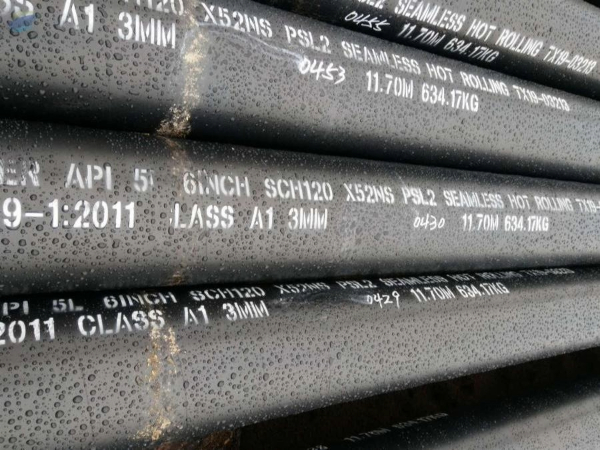
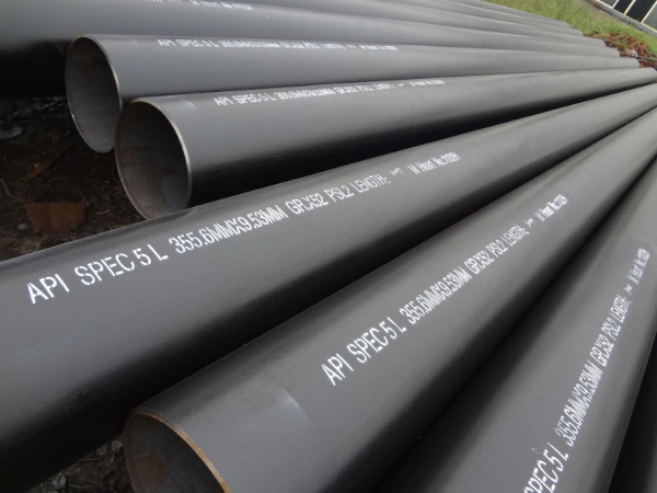
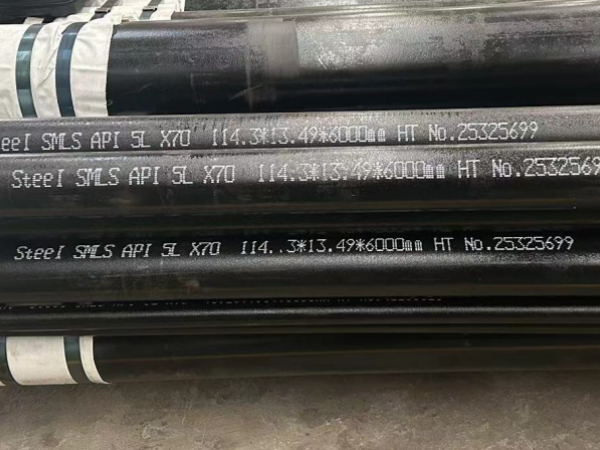
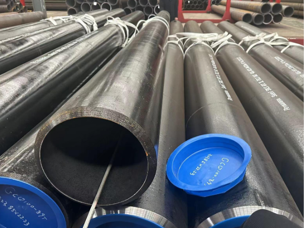
Seamless Steel Pipe
Carbon Seamless Steel Pipe
Boiler Pipe
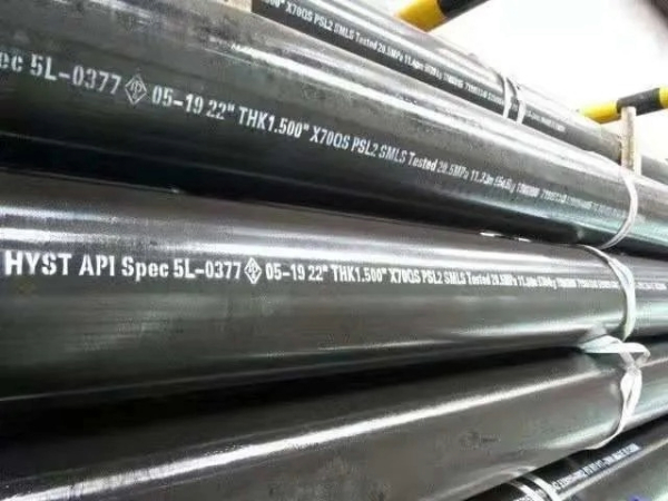
API 5L Line Pipe
Heat Exchanger Tubes
Mechanical Steel Pipe
Precision Steel Pipe
-
OCTG
Casing Pipe
Tubing Pipe
Drill Pipe
Drill Collars
Tubing And Casing Coupling
-
Structural Steel Section
Structural Steel Pipe
Square Steel Pipe
Rectangular Steel Tube
Scaffolding Pipe
H Beam
I Beam
U Beam
-
Stainless Steel Pipe
Stainless seamless pipes
Stainless Steel Welded Pipe
Duplex Steel Pipes
Super Duplex Steel Pipes
-
Coating Steel Pipe
2 / 3 PE Coated Pipe
Concrete Coating Pipe
FBE Coating Pipe
Galvanized Welded Pipe
Galvanized Seamless Pipe
-
Steel Metal
Steel Coil
Steel plate
-
Pipe Fittings
Tee
Reducer
Elbow
Flange
-
Special Products
Steel Sheet Pile
Screen Pipe
Pipe Clamps
Pipe Stands