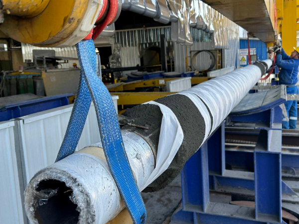
Concrete Coating Pipe
Without concrete weight coating (CWC), a 24" submarine pipeline in 200m seawater has net upward buoyancy of approximately 850 N/m — sufficient to cause lateral buckling under 2-knot bottom currents. Per DNV-OS-F101 Sec 7 D400, minimum 5% negative buoyancy margin requires concrete density ≥2400 kg/m³ at 65mm thickness for a 12.7mm WT pipe, rising to 3040 kg/m³ (hematite aggregate) for deepwater S-lay at 500m where 150mm coating is specified. Impact-spray application (ISO 21809-5 Clause 7.2, 80-100 m/s nozzle velocity) delivers 28-day compressive strength ≥40 MPa with galvanized wire mesh reinforcement (ASTM A572, 2-4mm wire, 100×100mm grid) embedded at mid-thickness. Compared to alternative weight coating methods (bolt-on concrete shells at 3× the cost and 40% lower impact resistance per DNV-RP-F113), CWC achieves the negative buoyancy, external impact protection (200 kN stinger roller load), and concrete-steel bond strength (≥1.5 MPa per ASTM C882) required for pipelines operated by Saipem, McDermott, and Allseas on projects from the North Sea to West Africa. Xenith Steel applies CWC on ERW, LSAW, and SSAW substrates OD 219-2020mm with full material traceability per ISO 9001:2015 and DNV-OS-F101 certification.- Products details
- Tolerance table
- Chemical composition
- Specification
Concrete Coating Pipe Introduction
|
Product: |
Concrete Coated Pipe, Concrete Weight Coating |
|
Application: |
Used for natural gas, petroleum, water & sewage, and pipe systems |
|
Size: |
OD: 219mm~2020mm |
|
WT: 5mm~25mm |
|
|
LENGTH: 4mtr, 6mtr, 12mtr, 18mtr, 21mtr |
|
|
Standard |
DIN 30670, DIN 30671, DIN 30678, SY/T0413-2002 etc. |
|
Pipe tape |
Submerged Arc Welded (LSAW/SSAW), Electric Resistance Welded |
|
End |
Plain End/Bevelled End, Burr Removed |
Dimensions Ranges for Concrete Coating Pipe
Mother pipe standards: API 5L Grade B to Grade 80. ISO 3183 Grade L245 to L555.
Diameter range: 6" to 60"
Pipe Thickness: SCH 20, SCH 40, SCH 80
Length: Up to 12 meters
Concrete Weight Coating Density
The concrete formulation can be tailored to any specified density specifications, normally are 140, 165, and 190 pounds per cubic foot, smaller or greater densities also applicable.
Density range: 1800-3450 kg/m3 (112-215 lbs/ft3)
Concrete compressive strength: From 3000 psi to 7200 psi. Up to 50 Mpa.
Concrete thickness: 1 inch to 8 inches. (25 mm to 200 mm)
Referred Standards
DNV-OS-F101: Submarine Pipeline Systems – SAWL 245, SAWL290, SAWL 320, SAWL 360, SAWL 415, SAWL 450, SAWL 485, SAWL 555
ISO 21809-5:2010: Petroleum and natural gas industries – External coatings for buried or submerged pipelines used in pipeline transportation systems – Part 5: External concrete coatings.
• ASTM C42 Standard Test Method for Obtaining and Testing Drilled Cores and Sawed Beams of Concrete
• ASTM C87 Test Methods for Effect of Impurities in Fine Aggregate on Strength of Mortar BS 1881 Methods of Testing Concrete
• ASTM C642 Standard Test Method for Specific Gravity, Absorption, and Voids in Hardened Concrete
• BS 3148 Test Methods for Water for Making Concrete
• BS 4449 Material Specification for Carbon Steel Bars for Concrete Reinforcement
• BS 4482 Hard Drawn Mild Steel Wire for the Reinforcement of Concrete
• BS 4483 Specification for Steel Fabric for the Reinforcement of Concrete
• ISO 4012 Test Specimen of Determination of Compressive Strength
Features of CWC pipe
CWC pipe consist of cement, water, aggregates and reinforcement materials, it's advantage is to fix the pipeline stably performances and provides effective mechanical protection. Compared with other insulation type like pipe-in-pipe, CWC pipe is more efficient in saving cost, easy the pipeline installation and convenient the operations.
Benefits of Concrete Coating Pipe
• Mechanical protection and negative buoyancy
• Anti-corrosion protection
• Excellent Compatibility
• Long-term adhesion to steel
• Well suited to reel laying methods
• High resistance to cathodic disbondment
• And much more
- Process
- Tests
- Tests
Radiographic testing
Radiographic testing is performed by recording degrees of absorption of penetrating radiation throughout the pipe wall. This results in generating a latent image of the object being under consideration or examined on a film that is later on chemically treated to transform the latent image into a permanent shadow image of internal and external defects in the pipeline. High intensity of radiation passes through the defected area when compared to regions without defects. Finally, these radiographer images can be evaluated by either professionals or automated computer vision systems.
Low-frequency electromagnetic testing (LFET)
In this process, the inspection process is accomplished by placing two ends of the electromagnetic driver on the metal surface, and a sensor is placed in between the two ends of the driver. The driver is a source of emitting low frequency (3-40Hz) alternating current signal and the sensors detect the magnetic field develops between the two poles of the driver. The principle of this testing is, "flaws in the steel structure alter the magnetic field", this alteration is recorded by the sensors in the form of amplitudes and variation in phase. If more flaws are found, the deviation in the magnetic signal will become wider and the sensors will record more shifts in the magnetic signal. Finally, the recorded signals transformed into a percentage of material loss by using numerical calculations.
Balanced field electromagnetic testing
This process the inspection of cylindrical storage tanks can be consummated by placing an electromagnetic probe near a metallic body. The divergence in the magnetic field is recorded; the vertical and horizontal sections of the signal are phase-shifted to reduce the noise in determining the magnetic field.
Longitudinal ultrasonic testing
In ultrasonic testing, a transducer emits high-frequency ultrasonic waves and propagates them across the material under investigation. Further, the transducers record the time lapse between the waves released and when the waves' echoes are received back to the transducers. In case of any flaws the time duration between the released and echoed waves condensed (comparing the absence of any flaws in the material). In ultrasonic testing, the particles in the material under consideration oscillate in response to the energy present in the ultrasonic waves propagated through it. The direction of the oscillation of particles is in the longitudinal direction.
Shear wave ultrasonic testing
The working principle of shear wave ultrasonic testing is the same to that of longitudinal ultrasonic testing. The only difference is the movement of particles is perpendicular to the direction of sound/ultrasonic waves. SWUT is also called angle beam testing, as it is employed to find out the flaws• dimensions and their depth in the material under consideration.
Frequently Asked Questions
What is concrete weight coating and why is it required for submarine pipelines?
• Per DNV-OS-F101 Sec 7 D400, submerged weight must exceed buoyancy by minimum 5% (static) and 2% (dynamic). CWC concrete density of 2400 kg/m³ at 65 mm thickness provides specific gravity ≥1.3 for a 24" OD pipe in 200 m depth.
• CWC also serves as mechanical armor against anchor drag, trawl gear impact up to 200 kN, and stinger roller contact during S-lay/J-lay installation.
• Xenith Steel supplies CWC pipe to offshore EPC contractors including Saipem, McDermott, and Allseas with full DNV type approval.
What standards govern CWC pipe manufacturing and quality control?
• Primary: DNV-OS-F101 (Submarine Pipeline Systems) and ISO 21809-5:2010 (External concrete coatings for buried/submerged pipelines — Part 5).
• Material testing: ASTM C42 (drilled cores), ASTM C642 (density/absorption/voids), ASTM C109 (28-day compressive strength), ASTM C78 (flexural strength).
• Reinforcement: ASTM A82 (steel wire), ASTM A185 (welded wire fabric), ASTM A641 (galvanized coating), BS 4449/4482/4483 (steel bars and fabric for concrete reinforcement).
• Application inspection: 25 kV DC holiday detection per NACE SP0188 on anticorrosion base before concrete spray, ±3 mm coating thickness per ISO 21809-5 Clause 8.2.
What density, thickness, and strength ranges can Xenith Steel achieve?
• Density: 1800–3450 kg/m³ (112–215 lb/ft³). Standard 2400 kg/m³ using silica aggregate; deepwater grades up to 3450 kg/m³ using hematite (Fe&sub2;O&sub3;) aggregate for maximum negative buoyancy.
• Thickness: 25–200 mm (1–8 inches), applied over FBE/3LPE anticorrosion base layer + galvanized steel reinforcement mesh (100×100 to 200×200 mm, 2–4 mm wire).
• Compressive strength: 3000–7200 psi (20–50 MPa) at 28 days per ASTM C109; flexural strength ≥4 MPa per ASTM C78.
• Mother pipe: API 5L Grade B to X80, OD 219–2020 mm, wall 5–25 mm, length up to 12 m. SMLS, LSAW, or SSAW substrate accepted.
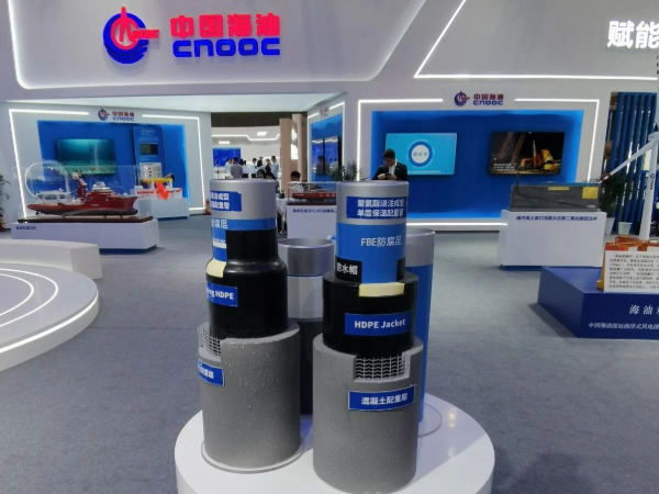
How does CWC differ from 3LPE or FBE anticorrosion coatings?
• Function: 3LPE/FBE provide anticorrosion only; CWC is a weight coating that provides negative buoyancy and mechanical protection — always applied over a primary anticorrosion layer, never as a substitute.
• Application method: CWC uses impact-spray (dry-mix pneumatically sprayed at 80–100 m/s per ISO 21809-5 Clause 7.2); 3LPE uses side-extrusion; FBE uses electrostatic spray.
• Cost comparison: CWC adds 30–60% to pipe weight and ~25–40% to cost vs bare pipe, but is 40–50% cheaper than pipe-in-pipe (PIP) for deepwater insulation and negative buoyancy.
• Field joint complexity: CWC requires concrete half-shells or PU-filled collars to maintain uniform negative buoyancy across joints — more complex than 3LPE heat-shrink sleeves alone.
How are CWC field joints protected and what cathodic protection is used?
• Shallow water (<200 m): heat shrink sleeve over girth weld + pre-molded concrete half-shell filled with cement grout, total weight within ±5% of parent pipe.
• Deepwater (>200 m): PU infill in prefabricated steel collar, density-matched to parent CWC to maintain uniform negative buoyancy across the entire pipeline.
• CP bracelet zinc anodes at 50 m intervals per DNV-RP-B401, electrically connected through the field joint with continuity tested at <0.1 Ω resistance.
• All field joint materials qualified per DNV-OS-F101 Sec 7 F300 with minimum 24-hour hydrostatic hold at 1.25× design pressure.
What is the typical lead time and documentation provided with each order?
• Standard CWC (25–75 mm, 2400 kg/m³): 8–12 weeks from pipe substrate availability. MOQ 500 m per OD/grade combination.
• Full documentation package: EN 10204 Type 3.1 mill test certificates, concrete mix design report with batch records, 28-day compressive strength results (ASTM C109), DNV/ABS type approval certificates, NACE SP0188 holiday detection report, and dimensional inspection records.
• Storage limit: 24 months onshore per DNV-OS-F101 Sec 7 E300 without re-certification. Supports at 6 m intervals. Xenith Steel applies ASTM C309 curing membrane to reduce carbonation penetration by 60% over standard curing.
- Packing & Delivery
- Tolerance table
- Chemical composition
MATERIALS
All concrete coating materials shall be furnished by the CONTRACTOR and shall consist of Portland cement, aggregate, reinforcing steel and water. These materials shall conform to the following specifications.
Cement
Cement shall conform to ASTM C150, Type II, or approved equal and shall be stored in a manner that will satisfactorily protect it from the elements. Cement that has hardened, partially hardened, or become lumpy shall not be used. Test certificates from the cement manufacturer shall be presented to the COMPANY for all cement.
Water
Water shall be clean and free from injurious amounts of oil, acid, alkali, salt, organic material or other deleterious substances. Seawater or water from stagnant swamps or excavations shall not be used. The COMPANY reserves the right to require the CONTRACTOR to test the water and have the results approved by the COMPANY prior to its use in the concrete mixture.
Sand (Silica Type)
Sand used shall be round grained and shall be obtained by sieving. It shall be free of injurious amounts of salt, alkali, deleterious substances or organic impurities. Suitability of the natural sand for making concrete shall be determined in accordance with the requirements of ASTM C33. The sand shall be well graded to the following sieve sizes:
U.S. Standard %
Sieve SizePassive
4100
880-100
1650-80
3025-55
505-30
1000-10
Aggregate
Well graded iron or barium ore shall be added to the aggregates to achieve the required density.
Concrete aggregates shall be clean, sound and free from injurious amounts of salt, alkali, organic impurities or other deleterious matter. Aggregates shall meet the requirements of ASTM C33. The aggregates shall be well graded to the following sieve sizes:
U.S. Standard %
Sieve Size Passive
3/8 in. 100
No. 4 80-90
No. 16 40-70
No. 50 10-30
No. 100 0-10
The aggregates shall be stored in a suitably graded area to ensure satisfactory draining of the stock pipe.
Reinforcing Steel
The reinforcement shall consist of a woven or welded wire mesh. Woven wire mesh shall be of the hexagonal type with extra longitudinal wires. Size of hexagonal mesh openings shall be 1.5 inches across the minimum dimensions. Welded wire mesh shall have openings of 1-inch by 2-inch.
The wire mesh shall be galvanized and the materials shall conform to ASTM A82, A90, A185 and A641 as applicable.
- Inquiry