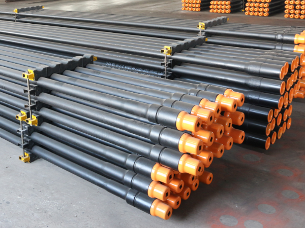
| Product: | Drill Pipe |
| Application: | Used for Mine, water well drilling, well drilling, coal and fore poling |
| Size: | OD: 2-3/8" to 7-5/8" |
| WT: 6.45-12.7mm | |
| LENGTH: R1, R2, R3 | |
| Pipe Standard: | API 5DP E75, X95, G105, S135 |
| Upset Style: | IU, EU, IEU |
| Connection: | NC26, NC31, NC38, NC40, NC46, NC50, 5 1/2FH.6 5/8FH. |
| Internal coating | TK34,TC2000, Arnco 100XT, 200XT, 300XT |
|
Product: |
Drill Pipe |
|
Application: |
Used for Mine, water well drilling, well drilling, coal and fore poling |
|
Size: |
OD: 2-3/8" to 7-5/8" |
|
WT: 6.45-12.7mm |
|
|
LENGTH: R1, R2, R3 |
|
|
Pipe Standard: |
API 5D,API 5DP E75, X95, G105, S135 |
|
Upset Style: |
IU, EU, IEU |
|
Connection: |
NC26, NC31, NC38, NC40, NC46, NC50, 5 1/2FH.6 5/8FH. |
|
Internal coating |
TK34,TC2000, Arnco 100XT, 200XT, 300XT |
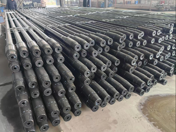
Drill collars are a component of the drill string that makes up part of the BHA. They are thicker-walled, heavier, and more rigid than drill pipes and are primarily used to weigh down the drill bit while dampening vibration and impact forces.
Proprietary grades often exceed the specifications set forth by API SPEC 5DP. Their enhanced performance properties are developed for sour service, critical service, and other user-defined requirements.
Sour service grades resist sulphide stress corrosion (SSC). SSC can occur when hydrogen sulfide is present. Ingress of hydrogen coupled with higher stresses, low temperatures, low pH, and high chloride content decreases the ductility of steel grades leaving them susceptible to crack propagation and failure.
Critical service grades resist corrosion when sweet gas or high concentrations of carbon dioxide are present. They are a cost effective alternative that is used in water injection applications.
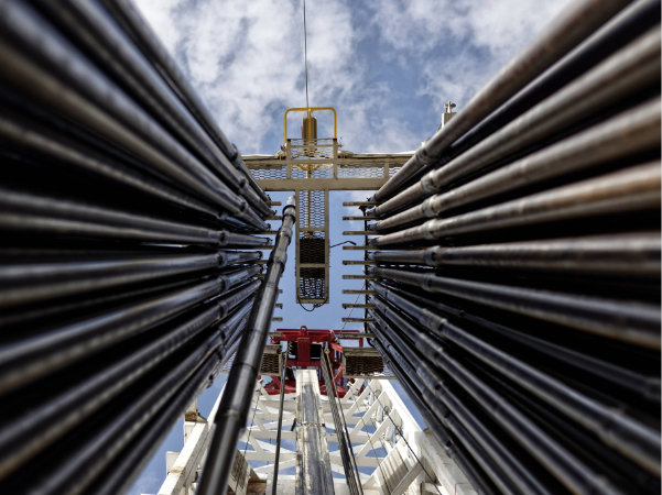
Drill pipe is manufactured according to standard specifications and is offered in nominal sizes. The two most important dimensional specifications are length and diameter.
The drill string is made up of several sections of drill pipe. The term "stand" refers to two or three sections of drill pipe that are fed into the well bore to complete 60 to 90 feet of drilling. Each segment of pipe, referred to as a "single", is classified by API into three distinct length ranges; R1, R2, and R3.
Range 1 (R1) is shortest in length, more common for sizing production tubing or casing, and ranges from 18 to 22 ft.
Range 2 (R2) is considered the standard length for drill pipe and ranges from 27 to 31 ft.
Range 3 (R3) is common in casing and also deployed in deep water drilling applications. The increased length decreases the number of tool joints in each stand of drill pipe. The fall back being that the load exerted on each tool joint is greater increasing wear and reducing the expected life of the drill pipe. R3 ranges from 38 to 45 ft.
The upset (thread-end finish) refers to the wall of the tool joint at the threaded connection. Drill pipe is offered with an internal upset (IU), an external upset (EU), or an internal-external upset (IEU).
IU - In an internal upset increased thickness along the inside walls compensate for the metal removed in threading with a uniform, straight outside wall.
EU - In an external upset the increased thickness along the outside diameter of the tubing compensates for the metal removed in threading with a straight bore.
IEU - In an internal-external upset thickness is increased along both the inside and outside walls of the pipe to compensate for the metal removed in threading.
Tool joints incorporate threaded connections. They include standard API threads as well as proprietary threads. Each type of threaded connection is specified by threads per inch (TPI) and it's taper. Common API tool joints include regular (REG), full-hole (FH), and internal-flush (IF).
Drill pipe manufacturing process includes steelmaking, continuous casting, hot rolling, upsetting, heat treatment, and quality inspection.
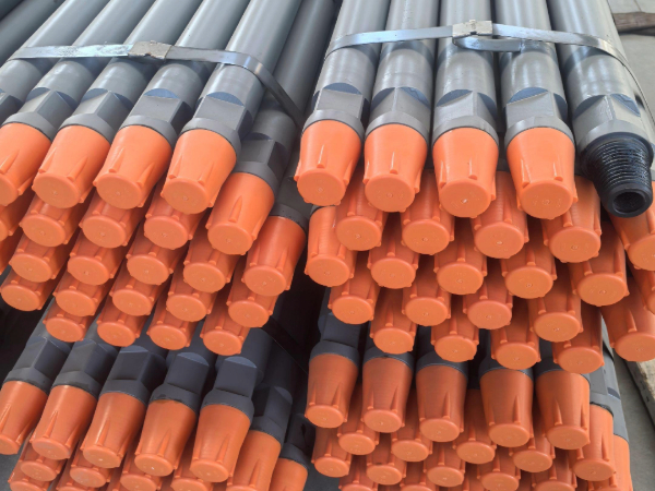
Drill pipes are bundled with steel strips, wrapped with waterproof plastic bags, and protected with thread caps. Loading into containers or bulk vessels.
|
API Drill Pipe Grade |
Minimum Yield Strength (psi) |
Minimum Tensile Strength (psi) |
|
E-75 |
75,000 |
100,000 |
|
X-95 |
95,000 |
105,000 |
|
G-105 |
105,000 |
115,000 |
|
S-135 |
135,000 |
145,000 |
|
Size designation |
Calculated weight |
Tool joint designation |
Calculated weight |
grade |
Wall thickness |
Upset ends |
||
|
in |
1b/ft |
Kg/m |
in |
mm |
||||
|
2 3/8 |
6.65 |
NC26 |
6.26 |
9.32 |
E.X.G.S |
0.28 |
7.11 |
EU |
|
2 7/8 |
10.4 |
NC31 |
9.72 |
14.48 |
E.X.G.S |
0.362 |
9.19 |
EU |
|
3 1/2 |
13.3 |
NC38 |
12.31 |
18.34 |
E.X.G.S |
0.368 |
9.35 |
EU |
|
3 1/2 |
15.5 |
NC38,NC40 |
14.63 |
21.79 |
E.X.G.S |
0.449 |
11.4 |
EU |
|
4 |
14 |
NC40,NC46 |
12.93 |
19.26 |
E.X.G.S |
0.33 |
8.38 |
IU,EU |
|
4 1/2 |
16.6 |
NC46,NC50 |
14.98 |
22.31 |
E.X.G.S |
0.337 |
8.56 |
EU,IEU |
|
4 1/2 |
20 |
NC46,NC50 |
18.69 |
27.84 |
E.X.G.S |
0.43 |
10.92 |
EU,IEU |
|
5 |
19.5 |
NC50,NC52 |
17.93 |
26.71 |
E.X.G.S |
0.362 |
9.19 |
IEU |
|
5 |
25.6 |
NC50,5 1/2FH |
24.03 |
35.79 |
E.X.G.S |
0.5 |
12.7 |
IEU |
|
5 1/2 |
21.9 |
5 1/2FH |
19.81 |
29.51 |
E.X.G.S |
0.361 |
9.17 |
IEU |
|
5 1/2 |
24.7 |
5 1/2FH |
22.54 |
33.57 |
E.X.G.S |
0.415 |
10.54 |
IEU |
|
6 5/8 |
25.2 |
6 5/8FH |
22.19 |
33 |
E.X.G.S |
0.33 |
8.387 |
IEU |
|
6 5/8 |
27.7 |
6 5/8FH |
24.21 |
41 |
E.X.G.S |
0.362 |
9.19 |
IEU |
Chemical Composition(%)
|
Grade |
Chemical composition |
|
|
P |
S |
|
|
E75 |
<0.015 |
<0.003 |
|
X95 |
<0.015 |
<0.003 |
|
G105 |
<0.015 |
<0.003 |
|
S135 |
<0.015 |
<0.003 |
|
Tool joint |
<0.015 |
<0.003 |
Mechanical Properties
|
Pipe body |
Grade |
Yield strength |
Tensile strength |
Elongation |
Hardness |
Full size charpy impact test(J) |
||||||
|
min |
max |
min |
min |
|||||||||
|
Psi |
MPa |
Psi |
MPa |
Psi |
MPa |
HBW |
HRC |
Average |
Single |
|||
|
E75 |
75000 |
517 |
105000 |
724 |
100000 |
689 |
625000A0.2/U0.9 |
- |
- |
80 |
65 |
|
|
X95 |
95000 |
655 |
125000 |
862 |
105000 |
724 |
- |
- |
80 |
65 |
||
|
G105 |
105000 |
724 |
135000 |
931 |
115000 |
793 |
- |
- |
80 |
65 |
||
|
S135 |
135000 |
931 |
165000 |
1138 |
145000 |
1000 |
- |
- |
80 |
65 |
||
|
Weld zone |
Tool joint |
120000 |
827.4 |
- |
- |
140000 |
965.3 |
=13% |
=285 |
- |
80 |
65 |
|
E75 |
75000 |
517 |
- |
- |
100000 |
689 |
- |
?37 |
40 |
27 |
||
|
X95 |
88000 |
609 |
- |
- |
103000 |
712 |
- |
?37 |
40 |
27 |
||
|
G105 |
95000 |
655 |
- |
- |
105000 |
724 |
- |
?37 |
40 |
27 |
||
|
S135 |
105000 |
724 |
- |
- |
115000 |
|
|
?37 |
40 |
27 |
||
Per API RP 7G Table 7 for 5" 19.5 lb/ft S-135: tensile capacity ~507,000 lbs (new pipe). Same size G105: ~395,000 lbs. At 15 lb/ft string weight with 50,000 lb overpull, G105 reaches ~23,000 ft; S135 hits ~30,500 ft — that's 7,500 ft of extra reach.
The S135 premium runs $8–12/ft. For a 20,000 ft string, that's $160,000 to $240,000 extra. Where it earns its keep: wells deeper than 23,000 ft, or any well where hookload exceeds 500,000 lbs. For a 15,000 ft vertical well, G105 is adequate and S135 is money wasted on capacity you'll never use.
API RP 7G Figure 7.2 gives the reversed-bending fatigue curve: for 5" G105 at 8°/100 ft DLS, roughly 200,000 cycles to failure. Each trip past that dogleg = 1 cycle per stand. At 50 trips (500 cycles total), you've consumed about 0.25% of the fatigue life — negligible. At 500 trips (5,000 cycles), you're at 2.5% — schedule MPI for joints that regularly pass through that zone.
Crossing 10,000 cycles in the same dogleg means roughly 60% cumulative fatigue. At that point move those joints to straight-hole sections or plan for retirement. Key rule: fatigue is cumulative — every trip past the same dogleg adds to the same counter, whether you drill fast or slow.
API Spec 7-2 §7.6 is clear: PWHT is mandatory for tool-joint-to-pipe friction welds. With proper PWHT at 590–650°C, Charpy V-notch at 0°C delivers 40–60 J across the weld zone, with hardness in the 32–35 HRC range. Without PWHT, the as-welded hardness hits 45–48 HRC and CVN drops to 15–25 J — well below the Spec 7-2 minimum of 27 J at 0°C.
Below −10°C, an as-welded joint falls under 20 J — that's brittle enough to propagate a crack under reversing bending loads. No reputable manufacturer skips this step. If a supplier quotes PWHT as optional, move on. There's no cost-saving justification for a joint that cracks on the first cold trip.
Erosion scales roughly as solids concentration × velocity² per API RP 14E. At 0.5% sand and 4.5 m/s annular velocity: tool joint ID loses about 0.5 mm after 1,200 rotating hours — acceptable for 2–3 wells. At 2% sand at the same velocity: same 0.5 mm loss in only 300 hours — that's 4× faster, dropping the tool joint below drift diameter in 1–2 wells.
Hardbanding (tungsten carbide overlay) stretches that 2–3×. Practical guidelines: below 0.5% sand, standard steel tool joints are fine. At 0.5–1% sand, run hardbanding as insurance. Above 1% sand, hardbanding is mandatory and inspection should tighten to every 100 rotating hours. Cost of hardbanding: ~$200–400 per joint — cheap vs. washout at 15,000 ft.
No. Per NACE MR0175 / ISO 15156 §7.3.3, SSC resistance for carbon steel requires hardness ≤30 HRC. S135 pipe body runs 35–38 HRC — no margin whatsoever. Tool joints run even harder. G105 at 30–32 HRC is borderline; it might pass or might not, depending on the heat. X95 at 28–30 HRC is the highest grade NACE MR0175 accepts, and even then you need SSC testing per NACE TM0177 Method A (80% SMYS, 720 hours in H₂S solution).
The honest bottom line: if H₂S partial pressure exceeds 0.05 bar, drop to X95 or lower. The extra 30,000 psi of tensile that S135 gives you is meaningless if the pipe shatters from sulfide stress cracking in a matter of hours. For sour service, specify X95 with NACE TM0177 verification, not S135 with hope.
Per API Spec 7-2 §9 and API 5DP §12, the 30-minute gate check:
(1) Tool joint dimensions: gauge 10 joints. OD per Spec 7-2 Table 3 tolerance +1%/‑0.5%. Thread taper 0.0625 in/ft checked with API plug and ring gauges.
(2) Hardness: 3 readings per tool joint, max 37 HRC per Spec 7-2 Table 8.
(3) Upset dimensions: check upset length per API 5DP Table 5 — external upset length tolerance ±1 inch.
(4) Straightness: ≤0.05% of overall length per Spec 7-2 §8.4.
(5) MTC: full chemistry + tensile + Charpy V-notch at 0°C (≥27 J average per Spec 7-2 §7.5).
Sampling plan: 10% of joints for dimensional, 5% for MPI, 100% visual. At roughly 3 minutes per joint on a 10% sample, you're done in 30 minutes. The three deal-breakers: tool joint hardness over 37 HRC, upset length out of tolerance, or missing CVN data on the MTC.