When a buried crude pipeline right-of-way crosses a desert zone with soil temperatures reaching 75-95°C at 2m depth, dual-layer FBE (DPS) per CSA Z245.20 Clause 6.2 becomes the only practical coating—its 500-1200µm total DFT at ≤110°C continuous exceeds single-layer FBE's 80°C ceiling (AWWA C213 Table 2) while holding cathodic disbondment ≤5mm at 23°C/28 days (ISO 21809-2 Table 2), verified per NACE TM0186. Xenith Steel applies FBE via electrostatic spray at 200-240°C over Sa 3 white metal blast (ISO 8501-1) with 50-100µm anchor profile, supporting OD 21.3-1620mm for oil/gas and offshore projects from our pipe coating facility in Cangzhou, meeting ADNOC and Saudi Aramco-grade specifications with 25kV DC holiday detection per NACE SP0188.
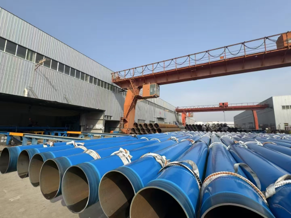
FBE Coating Pipe Introduction
Product:
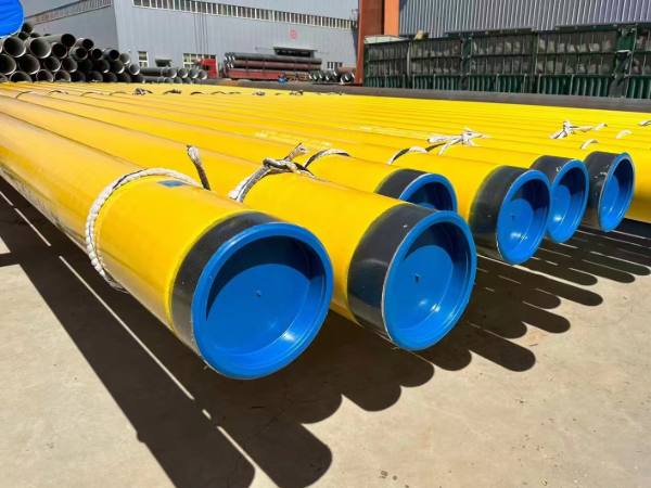
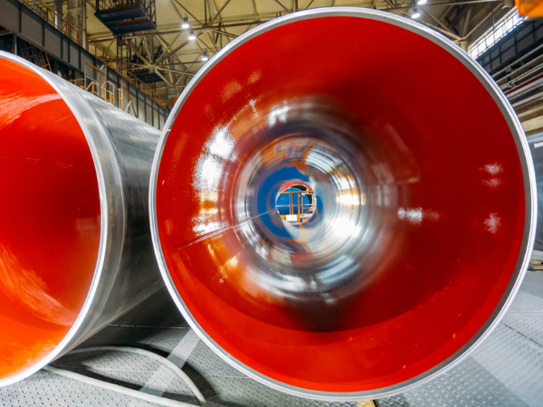
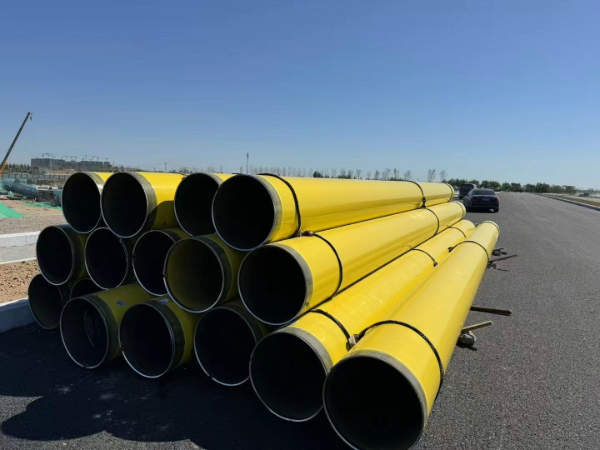
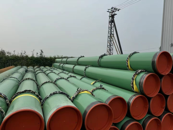
FBE (Fusion Bond Epoxy) Coated Pipe, Epoxy Coated Carbon Steel Pipe
Application:
Used for Coal mine,heat and power plant,oil and gas transmission
Standard:
DIN30670,CAN/CSA-Z245.21
Size:
OD:219-2000MM
Pakcing:
in bundles, in loose, Nylon Strip for each bundle for piece pipe
Color
RAL colors coating powder
Service:
anti-chemical corrosion and water resistance strong
Thickness Of FBE Coating Pipe
minimum 125 µm epoxy layer thickness
minimum 150 µm co-polymer layer thickness
minimum thickness of 1.8 mm to 4.7 mm polyethylene or polypropylene layer
minimum total layer thickness range
|
M kg/m |
Layer thickness in mm |
||||||||
|
Class A1 |
Class A2 |
Class A3 |
Class B1 |
Class B2 |
Class B3 |
Class C1 |
Class C2 |
Class C3 |
|
|
M = 15 |
1,8 |
2,1 |
2,6 |
1,3 |
1,8 |
2,3 |
1,3 |
1,7 |
2,1 |
|
15 < M = 50 |
2,0 |
2,4 |
3,0 |
1,5 |
2,1 |
2,7 |
1,5 |
1,9 |
2,4 |
|
50 < M = 130 |
2,4 |
2,8 |
3,5 |
1,8 |
2,5 |
3,1 |
1,8 |
2,3 |
2,8 |
|
130 < M = 300 |
2,6 |
3,2 |
3,9 |
2,2 |
2,8 |
3,5 |
2,2 |
2,5 |
3,2 |
|
300 < M |
3,2 |
3,8 |
4,7 |
2,5 |
3,3 |
4,2 |
2,5 |
3,0 |
3,8 |
|
Please note: The total required thickness may be reduced for SAW pipes by a maximum of 10% on joint seam. |
|||||||||
Minimum thickness of finished coating
|
Pipe Sizes (Specified OD) |
Minimum Coating Thickness Chart (mm) |
|
≤ 10 3 /4" (273.1 mm) |
2.5 |
|
> 12 3 /4" ( 323.9 mm) to ≤ 18" (457 mm) |
2.8 |
|
> 20" (508.0 mm) to = 30" (762 mm) |
3.0 |
|
> 32" (813.0 mm) |
3.3 |
Thickness of FBE coating on steel pipes
|
DN (mm) |
Epoxy Powder (µm) |
Adhesive Layer (µm) |
Min. Thickness on The Coating (mm) |
|
|
Common Level (G) |
Strengthen Level (S) |
|||
|
DN = 100 |
=120 |
=170 |
1.8 |
2.5 |
|
100 < DN =250 |
2.0 |
2.7 |
||
|
250 < DN < 500 |
2.2 |
2.9 |
||
|
500 =DN < 800 |
2.5 |
3.2 |
||
|
DN = 800 |
3.0 |
3.7 |
||
Features of FBE Coating Pipe
1. FBE coating is corrosion resistant and chemical resistant
Properties of a fusion-bonded epoxy (FBE) external pipeline coating can be significantly affected by the conditions under which the FBE powder has been stored. Nova, An Alberta Corporation, and 3M Co. undertook a program of evaluating easily run tests to determine the suitability of FBE powder. These tests are less time consuming than the most commonly used series of tests which involve evaluating laboratory-coated specimens or testing rings taken from production-coated pipe. Detailed here is that study of powder aging, coating application, and laboratory testing of aged powders and the subsequent coatings obtained from these powders. The results indicate that gel-time test was the only powder-test method which was both speedy and accurate.
The coating composition of Fusion Bonded Epoxy Steel Pipe comprises: (a) from about 50 wt % to about 90 wt % of at least one epoxy resin; (b) from about 1 wt % to about 30 wt % of at least one catechol novolak-type adhesion promoter; and (c) from about 0.1 wt % to about 5 wt % of magnesium oxide.
• Per ISO 21809-2 Table 1 and AWWA C213 Table 1: single-layer FBE applied at 200–240°C, DFT 250–500µm, service temperature ≤80°C continuous for buried pipelines.
• Dual-layer FBE (DPS) per CSA Z245.20 Clause 6.2: inner corrosion layer (epoxy + pigment) + outer mechanical layer reinforced with inorganic fillers, total DFT 500–1200µm, service temperature ≤110°C continuous.
• Impact resistance per ISO 21809-2 Table 4 at −30°C: DPS ≥15 J/mm vs single-layer ≥10 J/mm. Above 5 mm coating → impact energy increases linearly per mm.
• Xenith Steel offers both single-layer (standard buried) and DPS (high-temp/rocky terrain) with full ISO 21809-2 Type 3.1 certification.
• ISO 21809-2 Table 2: CD radius at 23°C/28 days/−1.5V ≤8 mm (single-layer), ≤5 mm (DPS). AWWA C213 Table 4: CD radius at 23°C/30 days/−1.5V ≤6.4 mm (0.25 in).
• NACE TM0186 Method A (48 h at 23°C/−1.5V): CD ≤10 mm for standard FBE; Xenith Steel targets ≤5 mm for all single-layer runs and ≤3 mm for DPS at 24 h.
• Test frequency per ISO 21809-2 Clause 8.3: one sample per 200 pipes or per production run, whichever is smaller. Rejection threshold: any CD >15 mm per NACE TM0186 Annex A.
• Temperature limits per ISO 21809-2 Clause 5.3 and ISO 21809-3 Clause 5.2: FBE single-layer ≤80°C, DPS ≤110°C, 3LPE (PE topcoat) ≤60°C per DIN 30670, 3LPP (PP topcoat) ≤110°C per DIN 30678.
• CP compatibility per NACE SP0169 Section 6.2.3.2: FBE is ion-permeable (10¹–10³ Ω·cm²) allowing CP current to reach steel surface; 3LPE exhibits cathodic shielding at >10&sup5; Ω·cm² per NACE 1C192, reducing CP effectiveness by up to 80% in high-resistivity soil.
• Cost comparison per NACE 10A392: FBE 20–30% lower installed cost than 3LPE for diameters ≤36″. Above 36″, 3LPE side-extrusion becomes more economical.
• Abrasive blast per AWWA C213 Section 4.2: white metal to Sa 3 (ISO 8501-1), anchor profile 50–100 µm (2–4 mils) per ISO 8503-1, maximum chloride contamination ≤20 mg/m² per ISO 8502-6.
• Preheat per NACE RP0288 Section 4.3: steel surface 200–240°C verified by contact pyrometer at 3 points per pipe. Maximum 4-hour window between blast and coating at <85% RH per NACE RP0288 Section 5.1.
• Electrostatic spray application: gun voltage 60–100 kV, powder feed rate 20–40 kg/h, line speed matched to achieve minimum gel time of 12 s at 230°C per ISO 21809-2 Clause 7.2.
• Minimum DFT after cure: 250 µm per ISO 21809-2 Clause 7.1, measured at 10 points per pipe per ISO 2808. Reject if any point below 200 µm.
• Continuous service limits: single-layer FBE ≤80°C per AWWA C213 Table 2; DPS ≤110°C per CSA Z245.20 Table 1. Short-term excursions per ISO 21809-2 Clause 5.4.2: DPS ≤120°C for ≤100 h cumulative, single-layer ≤95°C for ≤50 h.
• Low-temperature handling per NACE SP0394: FBE remains intact at −40°C for handling and installation if not subjected to direct impact >5 J. Below −40°C, heat shrink sleeve primer becomes brittle.
• Above 110°C continuous: switch to 3LPP (DIN 30678, ≤110°C) or multi-layer FBE + PP system per ISO 21809-2 Annex C. Xenith Steel supplies FBE for 80–110°C service on customer specification.
• Repair methods per ISO 21809-2 Clause 9.3: (a) liquid epoxy two-part coating brush-applied to Sa 2.5 blasted surface (ISO 8501-1), minimum DFT 500 µm; (b) heat shrink sleeve with FBE primer layer per DIN 30672, peel strength ≥40 N/cm at 23°C.
• Holiday detection per NACE SP0188: 100% DC spark test at 5 V/µm coating thickness, maximum allowed holiday 1 per 10 m². Any holiday >3 mm → repair by Method (a) above.
• Adhesion per ASTM D4541: minimum pull-off strength 1,000 psi (6.9 MPa) at 23°C. Test frequency: 1 per 50 field joints per NACE SP0394 Section 7.3.
• CD verification per NACE TM0186 at 23°C/48 h/−1.5V on field joint: ≤10 mm for both Methods (a) and (b).