|
Product Name |
Steel I Beam |
|
Material |
Q235/Q235B/Q345/Q345B/Q195/St37/St42/St37-2/St35.4/St52.4/St35 |
|
Keyword |
High Strength Steel I Beam |
|
Surface |
Black |
|
Technology |
Cold Rolled / Hot Rolled |
|
Steel Grade |
SGCC/SGCD/SGCE/DX51D/DX52D/S250GD/S280GD/S350GD/G550/SPCC |
|
Packing |
Standard Seaworthy Packing |
|
Product Name |
Steel I Beam |
|
Material |
Q235/Q235B/Q345/Q345B/Q195/St37/St42/St37-2/St35.4/St52.4/St35 |
|
Keyword |
High Strength Steel I Beam |
|
Surface |
Black |
|
Technology |
Cold Rolled / Hot Rolled |
|
Steel Grade |
SGCC/SGCD/SGCE/DX51D/DX52D/S250GD/S280GD/S350GD/G550/SPCC |
|
Packing |
Standard Seaworthy Packing |
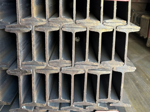
Steel I Beam Applications:
Support beams for construction,machinery, shipbuilding, bridge, boiler, pressure vessel, facilities and engineering
Support steel channels, steel angles
Workplace platforms
Factory shops, warehouses
Truck bed framing
A load is applied at the center of a beam using weights, and the resulting midspan deflection is measured. The elastic stiffness of the beam is determined and compared to published values for various beam materials and cross sectional shapes.
ASTM A6/A6M-22 §12.2 specifies S-shape I beam tolerances: depth ±3.2mm for ≤ 305mm, ±4.8mm for > 305mm. Flange width ±3.2mm for ≤ 168mm, ±4.8mm for > 168mm. Web thickness +0.76/-0.38mm per §12.4. Flange taper tolerance: the 1:6 inner slope must not exceed 2.5° deviation per §12.6. Camber: 1/1000 of length per §12.7. Sweep: 6mm max per 10m. EN 10034:1993 Table 1: depth ±2mm for ≤ 180mm, ±3mm for 180-400mm. JIS G3192:2009 §6.1: depth ±2mm for ≤ 400mm. Mass tolerance per ASTM A6 §13: ±2.5% individual, ±1.75% average for orders over 20 tons.
ASTM A992/A992M-22 is the preferred specification for structural I beams per AISC 15th Ed §2.1. Yield: 345-450 MPa (A36: 250 MPa per ASTM A36/A36M-19 §5). Tensile: 450-620 MPa (A36: 400-550 MPa). Yield/tensile ratio ≤ 0.85 per §6. Elongation ≥ 18% in 200mm per ASTM A370 §7. Charpy V-notch optional per S5 (≥ 27 J at 21°C). EN 10025-2 S355J2: yield ≥ 355 MPa (t ≤ 16mm), ≥ 345 MPa (16-40mm) per §6, impact ≥ 27 J at -20°C per §7. For bridge applications, A709 Gr50 requires additional through-thickness tensile testing per ASTM A6 §14.
The universal mill hot-rolling process for I beams uses three stands: breakdown rougher, universal rougher, and finishing stand. Per EN 10034:1993 §8.1, the rolling temperature range is 1100-1250°C for reheating, with finishing temperature at 950-1050°C to achieve fine grain structure. The tapered flange profile (1:6 inner slope per ASTM A6 §12.6) is formed by angled rolls, while the web is rolled between horizontal rolls. Controlled cooling rate per ASTM A6 supplementary S14 ensures straightness ≤ 1/1000. Normalizing rolling (TMCP per EN 10025-4) achieves minimum 0.25% elongation with ferrite-pearlite microstructure as verified by ASTM E112 grain size 8 or finer.
Our QC follows ASTM A6/A6M-22 §19 and EN 10204:2004. Six mandatory checks per lot:
(1) Dimensional inspection per §12 — depth, flange width, web thickness, flange squareness, camber, sweep using calibrated gauges per ISO 6508-1.
(2) Tensile testing per ASTM A370 §7 on longitudinal specimens — yield, tensile, elongation.
(3) Chemical analysis per ASTM E415 for C, Mn, P, S, Si — CEV ≤ 0.45% per IIW formula as per EN 10025-1 §7.4.
(4) Bend test per ASTM A6 §20.3 — 180° bend around 1.5t mandrel.
(5) Surface inspection per ASTM A6 §11 — no laps, scabs, or seams exceeding 0.5mm depth.
(6) Ultrasonic testing per ASTM A435 optional for critical applications. MTC per EN 10204 3.1 includes all results.
(1) Flexural design per AISC 360-22 §F2: For compact I beam sections (λ ≤ λp per Table B4.1b), nominal flexural strength Mn = Mp = Fy × Zx, where Fy = 345 MPa (A992) and Zx is the plastic section modulus. ASD allowable: Mmax ≤ Fb × Sx with Fb = 0.66 Fy for compact (Table F2-1).
(2) Shear per §G2: φv = 0.9 (LRFD), Ωv = 1.67 (ASD). Nominal shear Vn = 0.6 Fy × Aw × Cv where Aw = d × tw. For h/tw ≤ 2.24√(E/Fy), Cv = 1.0.
(3) Deflection per AISC 15th Ed §L3: Live load deflection limit L/360 for roofs, L/240 for floors per Table L3.1. Total load L/240 minimum.
(4) Compression per §E3: For flexural buckling, φc = 0.9 (LRFD). Critical stress Fcr per Equations E3-2 through E3-4 depending on KL/r ratio against 4.71√(E/Fy).
Packaging per ASTM A6 §16: beams bundled in multi-piece groups (2-8 beams per bundle depending on weight), steel straps at 2m intervals with edge protectors, wooden dunnage separating layers for surface protection. Waterproof covers (VCI paper + PE film) for sea shipments per ISO 9227. Loading: 20ft container 18-22 tons (40ft: 26-28 tons) using dunnage and blocking per IMO/ILO guidelines. Third-party inspection by SGS, BV, or ABS per ISO 2859-1 AQL 4.0. Custom lengths from 3m to 21m with 2mm tolerances per EN 10034 §9. Storage recommendation: beams stored on sleepers with 300mm ground clearance to prevent corrosion per ISO 8501-1 C grade.
The dimensions do not exceed the acceptable tolerance of±6 mm in either of the primary axes
A992/A572-50 Standard I Beam Chemical Composition
Carbon, Max - 0.23%
Manganese - 0.50 to 1.60%
Silicon, Max - 0.40%
Vanadium, Max - 0.15%
Columbium, Max-0.05%
Phosphorus, Max-0.035
Sulfur, Max-0.045%
|
A36 Steel I Beam Chemical Composition |
||||||
|
Steel grade |
Styles |
Carbon, max, % |
Manganese, % |
Phosphorus, max, % |
Sulfur, max, % |
Silicon, % |
|
A36 |
Steel sections |
0.26 |
-- |
0.04 |
0.05 |
=0.40 |
Note: Copper content is available when your order is specified.
|
ASTM A588 Steel I Beam Chemical Composition (Heat Analysis) |
|||||||||
|
Steel grade |
Carbon, max, % |
Manganese, % |
Phosphorus, max, % |
Sulfur, max, % |
Silicon, % |
Nickel, max, % |
Chromium, % |
Copper |
Vanadium, % |
|
A588 grade A |
0.19 |
0.80 - 1.25 |
0.04 |
0.05 |
0.30 - 0.65 |
0.40 |
0.40 - 0.65 |
0.25 - 0.40 |
0.02 - 0.10 |