Xenith Steel
Xenith Steel
Steel pipe pile with driving shoe
Open-ended pipe pile for marine use
Pipe pile bundle at yard

Steel Pipe Piles

When foundation loads exceed soil bearing capacity at 30-50m depth, driven steel pipe piles transfer structural loads through skin friction and end-bearing to competent strata. OD 219-1626mm (8.625-64"), WT 6-70mm (0.250-2.75"), ASTM A252 Gr.1-3 / API 5L Gr.B-X70. Open-ended (unplugged) or closed-ended (plugged) configurations. Unlike precast concrete piles, steel pipe piles offer higher driving resistance, full-length splice weldability, and PDA-monitored capacity verification per ASTM D4945. AWS D1.1 certified welders. Supplied to offshore platforms, bridge piers, and marine terminals for COOEC, Samsung Heavy Industries, and Hyundai Engineering & Construction from our LSAW pipe factory in Cangzhou, Hebei, China.

Scope

Steel pipe piling for permanent, structural load-carrying member or as a shell to form cast-in-place concrete piles.

Specification

ASTM A252, Grades 2 and 3/modified to 50 ksi min. yield

Size (OD)

8.625, 10.750 and 12.750

Gauge/Wall Thickness

0.250, 0.313, 0.375 and 0.500 (nominal)

Strength/Elongation Properties

Yield: 50 ksi min., 60 ksi min., 75 ksi min., 80 ksi min. Aim to.

Tensile: 66 ksi min. Elongation: 20% min.

Straightness Tolerance

1/8” x length (in feet), divided by five

  • Products details
  • Tolerance table
  • Chemical composition
  • Specification

Piling Steel Pipe Specification

Scope

Steel pipe piling for permanent, structural load-carrying member or as a shell to form cast-in-place concrete piles.

Specification

ASTM A252, Grades 2 and 3/modified to 50 ksi min. yield

Size (OD)

8.625, 10.750 and 12.750

Gauge/Wall Thickness

0.250, 0.313, 0.375 and 0.500 (nominal)

Strength/Elongation Properties

Yield: 50 ksi min., 60 ksi min., 75 ksi min., 80 ksi min. Aim to.

Tensile: 66 ksi min. Elongation: 20% min.

Straightness Tolerance

1/8” x length (in feet), divided by five


Weight Tolerance

Weight must not vary more than 15% over or 5% under.

Piling weight controlled by utilizing minimum-gauge coil stock.

Searing does not weigh each individual length of pipe.

Chemical Composition

Carbon: 0.23 max. Manganese: 1.35 max. Meets ASTM A252

Carbon Equivalent (CE)

0.45 max (per AWS D1.1)

Weldability

AWD D1.1 base metal

Can be welded with AWS prequalified welding procedures

Testing

ASTM A370: In-house flattening and cone test per heat

Material Test Reports

Material test reports are furnished for each length of pipe.

Steel mill coil certifications/gauge certifications available upon request.

Marking/ID Stamp

Ink stenciling on one side of the OD, ID stamping when requested


STRENGTH LEVELS

GRADE 2

GRADE 3

Yield Strength

35,000 psi min.

45,000 psi min.

Tensile Strength

60,000 psi min.

66,000 psi min.

Elongation % in 2” Min.

25

20

Meets AWS D1.1 Base Metal Welding requirements

Yes

Yes

Advantages of Pipe Piles

As opposed to other options for deep foundations, pipe piles offer several advantages.

1. They lower costs because they are capable of being tailored to meet specific load bearing requirements.

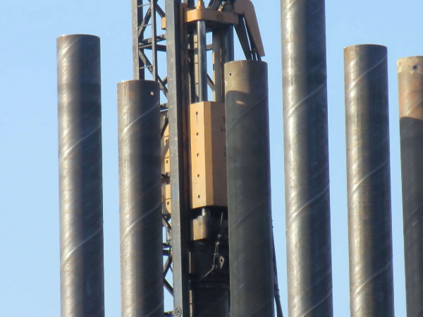
2. They are simple to drive and install, and they’re easy to inspect and test before use.

3. They are sturdy and unlikely to crack or otherwise get damaged while they are being driven into the ground.

4. Additionally, pipe piles can be added to bolster foundation support after construction and during various phases of construction.


Application of Steel Pipe Piles

Pipe piles can be used for the creation of the following:

• Building foundations

• Bridge foundations

• Highway foundations

• Marine structure foundations

• Dock foundations

• Offshore construction foundations

• Railway foundations

• Oilfield construction foundations

• Communication tower foundations

• Column foundations


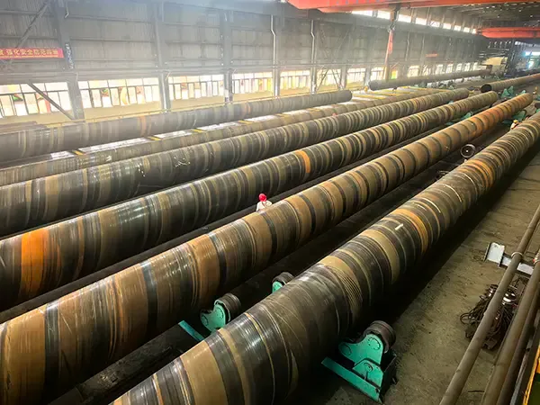
Types of Piling Steel Pipes

Based on the different soil environments and requirements, Pipe piling could be divided in open end pile (Unplugged pipe pile) and close end pile pipe(Plugged pipe pile).
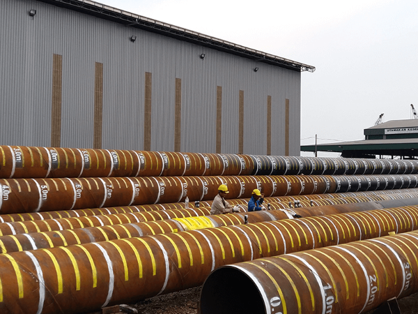

Process

As soon as we receive your pipe pile designs, our fabrication division will begin creating your pipe piling. Fabrication is usually carried out in these steps:

1. Cut out and etch steel plate with CNC plasma cutters.

2. Bevel the plate ends (if required) to ensure quality welding.

3. Roll the plate into cylinders.

4. Weld the longitudinal seam of the cylinder.

5. Connect cylinders by welding the circumferential seam using our sophisticated submerged arc process.

6. Forward the pipe pile to our testing division, where the completed pipe piling must pass rigorous inspection before shipment to the job site.

7. If project specifies, the steel is blasted and coated to increase longevity.


Tests

Our Testing Capabilities Include:

• Visual inspection and step by step monitoring of all processes to ensure the best possible quality

• Radiographic Testing (RT)

• Ultrasonic Testing (UT)

• Dye Penetrant Testing (PT)

• Magnetic Particle Testing (MT)

• Heat treating and stress relieving

• Hardness Testing

• Impact Testing

• Positive Material Identification (PMI)

• Leak Testing

• Hydrostatic Testing, up to 2,500 psig

• Environmental monitoring and reporting

• Soluble Salt Testing

• Full blast and lining profile measuring

• Dry film thickness testing

• Adhesion Testing

• Lining continuity (holiday) testing

  • Packing & Delivery
  • Tolerance table

Piling Steel Pipe Weight and Dimension Tolerances

Pipe pile weights per units (Feet, meter or lengths)
Tolerance allowed: A252 pipe pile weight shall be in +15% or -5% of theoretic weight. OD tolerances at +/-1%, wall thickness +/- 12%.
Lengths: As specified SRL, DRL, or fixed length 20 ft or 40 ft and customized.


Permissible Variations for A252 Piling Steel Pipe

Wall thickness: Not more than 12.5% under the nominal wall thickness specified.

Weights per foot: The weight of any individual length of pipe shall not vary more than 15% over or 5% under the weight specified. Each individual length shall be weighed separately.

Outside diameter: Shall not vary more than plus or minus 1% from the diameter specified.

TOLERANCES

ALL GRADES

OD Size


>1.9 - 2.5 incl.

+/- 1%

>2.5 - 3.5 incl.

+/- 1%

>3.5 - 5.5 incl.

+/- 1%

>5.5

+/- 1%

Wall Thickness

–12.5%

Weight

+15% / –5%

Straightness (max. allowed)

Not specified

  • Chemical composition

Chemical Requirements for A252 Steel Pipe


Phosphorus

Seamless and ERW Welded

Max% 0.050

Chemical Composition

Carbon: 0.23 max. Manganese: 1.35 max. Meets ASTM A252

CHEMISTRY LEVELS

ALL GRADES

Carbon

N/A

Manganese

N/A

Phosphorus

0.050 max.

Sulphur

N/A

Silicon

N/A

Grain Refining Elements

N/A

Frequently Asked Questions

1. How is the axial bearing capacity of driven piles calculated per API 2A-WSD?

Per API 2A-WSD Section 6.3.2, ultimate axial capacity Qu = Qs + Qt with safety factor 2.0 for static design.

Skin friction (Qs) per API 2A-WSD Section 6.3.3:

(1) Alpha method (clay): Qs = α × Su × As, where α = 0.5 for Su ≤ 25kPa, α = 0.5-0.25 for Su = 25-150kPa, α = 0.25 for Su ≥ 150kPa per API 2A-WSD Table 6.3.3-1

(2) Beta method (sand): Qs = β × σ'v × As, where β = 0.25-0.35 for low-density, 0.35-0.55 for medium, 0.55-0.65 for high-density sand per API 2A-WSD Table 6.3.3-2

Tip resistance (Qt) per API 2A-WSD Section 6.3.4:

(1) Cohesionless: Qt = Nq × σ'v × At, Nq = 8-50 per API 2A-WSD Figure 6.3.4-1 based on friction angle φ = 28-40°

(2) Cohesive: Qt = Su × Nc × At, Nc = 9.0 for deep foundations per Skempton (confirmed by API 2A-WSD Section 6.3.4.2)

Static load test acceptance per ASTM D1143/D1143M-07 Section 7.2: maintain test load at 200% design load for minimum 12h with creep ≤ 0.25mm/h over final 1h. Load-settlement curve per Section 8: Davisson offset limit = 0.15in + (D/120) for pipe piles.

Site investigation per ASTM D1586: SPT N-value every 1.5m to 2× pile embedment depth. CPT per ASTM D5778: minimum qc profile required for β method calibration.

2. How does soil plugging affect open-ended pipe pile capacity per API 2A-WSD?

Per API 2A-WSD Section 6.5.1, open-ended pipe pile capacity depends on plugging ratio PLR = (internal soil column length) / (pile penetration depth). Three plugging states control end-bearing contribution:

(1) Unplugged (PLR < 0.7): soil column height < 70% of penetration — internal friction Qs_internal contributes but no tip plug. Tip capacity calculated on steel annulus area only per API 2A-WSD Eq 6.5.1-1.

(2) Partially plugged (PLR = 0.7-0.95): soil compresses inside, internal friction develops but soil core does not fully engage at tip. Qplug = Qs_internal + 0.5 × Qt_plug per ISO 19901-4 Section 8.3.3.

(3) Fully plugged (PLR ≥ 0.95): soil column nearly full penetration — pipe behaves as closed-ended. Full cross-section tip resistance per API 2A-WSD Section 6.5.2: Qt = Nq × σ'v × (π × D²/4).

Plugging criteria per API 2A-WSD Table 6.5.2-1: plug will form when D₅₀ (mean particle size) / D (pile OD) ≥ 0.002 for sand. For ID > 900mm in loose sand, plug rarely forms — use unplugged calculation per Section 6.5.1.2.

Incremental filling ratio (IFR) per ISO 19901-4 Annex C: IFR = d(soil column)/d(penetration) — IFR ≤ 0.5 typically indicates plugging; IFR ≥ 0.9 means free soil entry. PDA measurements per ASTM D4945 confirm plugging state during final driving.

3. How is pile driving analyzer (PDA) used for quality control per ASTM D4945?

PDA per ASTM D4945 Section 5.1 measures real-time pile response during driving:

Measurements:

(1) Strain — force at pile head gages per Section 7.2 — strain resolution ±0.01%

(2) Acceleration — velocity integration per Section 7.3 — double integration for displacement

(3) Max compression and tension stress — per API 2A-WSD Section 6.6.3: compression ≤ 0.9Fy, tension ≤ 0.9Fy to prevent yield damage

(4) CAPWAP analysis per ASTM D4945 Annex A — signal matching of measured force vs velocity to derive shaft resistance distribution and tip bearing

Driving criteria per API 2A-WSD Section 6.6.2:

(1) Blow count / final set — refusal at 5mm per 10 blows for sand (Class 1), measured by PDA displacement transducer

(2) Hammer energy — computed from force × velocity integral per Section 8.1.2: EH ≥ 60kJ for Class 1 driving

(3) Pile impedance match — hammer energy transfer efficiency ≥ 40% per GRLWEAP analysis for diesel/hydraulic hammers

Restrike criteria per Section 6.6.5: perform restrike ≥ 24h after end of initial driving. Setup ratio SR = capacity_restrike / capacity_EOID — sand SR = 1.0-1.15, clay SR = 1.5-4.0 per API 2A-WSD Figure 6.6.5-1. Minimum restrike blows: 10-20 blows or until final set rate < 1mm/blow.

4. What is negative skin friction (downdrag) and how is it calculated per API 2A-WSD?

Per API 2A-WSD Section 6.4.3, negative skin friction (NSF) is the downward drag force from consolidating soil surrounding the pile shaft. Neutral plane (NP) per ISO 19901-4 Section 9.5 — the depth where soil settlement equals pile settlement; NSF acts above NP, positive friction below.

NSF calculation per API 2A-WSD Eq 6.4.3-2: F_nsf = β × σ'v × As, where β = 0.10-0.25 for normally consolidated clay and 0.15-0.30 for fill material. For soft sensitive clay (Su < 25kPa), α-red = 0.3-0.5 × Su (reduced from α = 1.0 for positive skin friction per API 2A-WSD Section 6.4.3.2).

Trigger criteria per API 2A-WSD Section 6.4.3.1: NSF must be considered when surface settlement exceeds 10mm or when fill height > 1m within pile influence zone (≈ 3 × pile group width).

Peat/organic layers per Eurocode 7 Section 7.3.2.2: compression index Cc ≥ 0.3, settlement up to 200mm per meter of peat thickness — NSF can reach 50-80% of positive shaft capacity.

Mitigation per API RP 2A Section 6.4.3.3:

(1) Bitumen coating — reduces NSF adhesion to 5-10kPa per tested interface per ASTM D5321; shear strength ≤ 10kPa for bitumen temperature range -10°C to +40°C

(2) Sleeved pile section — separates shaft from surrounding soil for top 5-10m

(3) Pre-drilling/jetting — reduces driving resistance but does not eliminate NSF

Design acceptance: per API 2A-WSD Section 6.4.3.4, NSF load combined with axial load must not exceed structural capacity with safety factor ≥ 1.5. For large groups, group NSF = 0.5-0.8 × individual NSF due to arching per API 2A-WSD Figure 6.4.3.

5. How are pile splices designed for full tensile strength?

Pile splices must develop 100% pipe strength:

Splice types:

(1) Full-penetration groove weld — most common, develops 100%

(2) Partial-penetration groove — not recommended for tension

(3) Sleeve weld — full circumference required

Groove weld design:

(1) Full V or U groove — complete root penetration

(2) Back-gouging — remove root flaws for complete fusion

(3) Multi-pass welding — fill groove completely

Strength verification:

Tensile test of splice joint (full pipe vs spliced pipe)

Acceptance: ≥ 100% of pipe minimum yield

Xenith Steel welders hold AWS D1.1 certification.

6. What driving criteria apply per API 2A-WSD for different soil conditions?

Per API 2A-WSD Section 6.6 and EN 12699 Section 7.5, driving criteria are soil-dependent:

Sand and gravel (Driving Class 1 per API 2A-WSD Table 6.6-1):

(1) Blow count criteria per API 2A-WSD Section 6.6.2.1: final set ≤ 10mm per 10 blows (EH ≥ 60kJ hammer energy). Refusal at 5mm per 10 blows with max stress ≤ 0.9 × yield per Section 6.6.3.

(2) Driving stress limits per API 2A-WSD Eq 6.6.3-1: compression stress σc ≤ 0.9Fy (Fy = min yield), tension stress σt ≤ 0.9Fy during hammer rebound. Measured by PDA per ASTM D4945 Section 7.5 — max stress recorded at pile head gages.

(3) Setup factor per API 2A-WSD Section 6.6.4: sand gains 0-15% capacity in 24h (negligible setup); restrike after ≥ 24h confirms final capacity per API 2A-WSD Section 6.6.5.

Clay (Driving Class 2):

(1) Sensitivity ratio St = Su_undisturbed / Su_remolded per ASTM D4648 — high sensitivity clay (St > 8) gains 100-300% setup over 7-30 days per API 2A-WSD Figure 6.6.5-1

(2) Pore pressure dissipation: Blow counts may drop 30-50%, then rise as pore pressure dissipates. Drive must continue to 2× estimated depth per API 2A-WSD Section 6.6.2.2 to bypass remolded zone.

(3) Soil adhesion on pipe wall: per API 2A-WSD Table 6.6-2, adhesion stress τ_ad = 5-30kPa for clay end-bearing (reduces driveability).

Rock (Driving Class 4):

(1) Predrilling per API 2A-WSD Section 6.6.6.1: socket depth = 1-3 × OD into competent bedrock (UCS ≥ 50MPa per ASTM D7012). Minimum rock socket length for end-bearing: 1.5 × OD when UCS = 50-100MPa.

(2) Rock shoe (drive shoe) per EN 12699 Section 7.4.2: hardened steel tip with 30-45° bevel, wall thickness 1.5× pipe WT. Maximum driving stress with rock shoe ≤ 0.75Fy per API 2A-WSD Section 6.6.6.2.

(3) Wave equation analysis (GRLWEAP) per ASTM D4945 Annex A: required for all Class 4 driving — match hammer energy, cushion stiffness, and pile impedance within 25% of measured values per Section A.3.