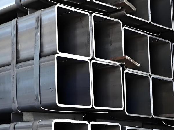
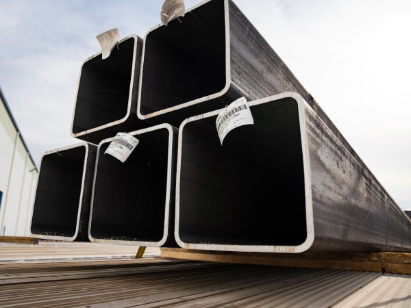
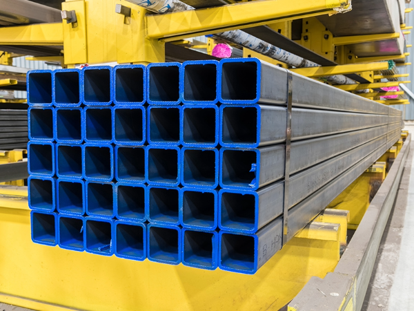
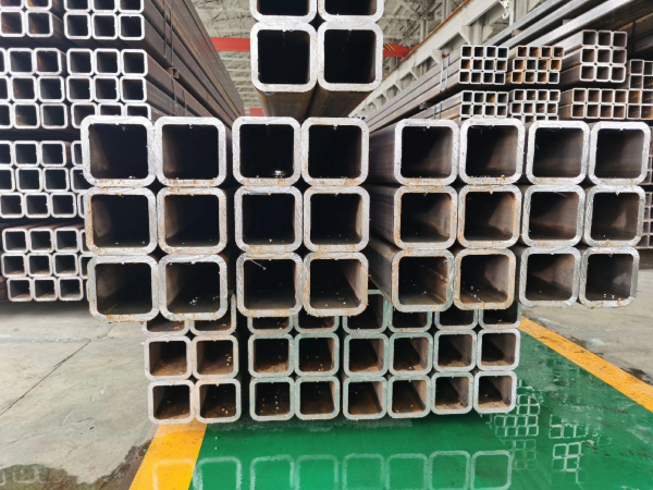
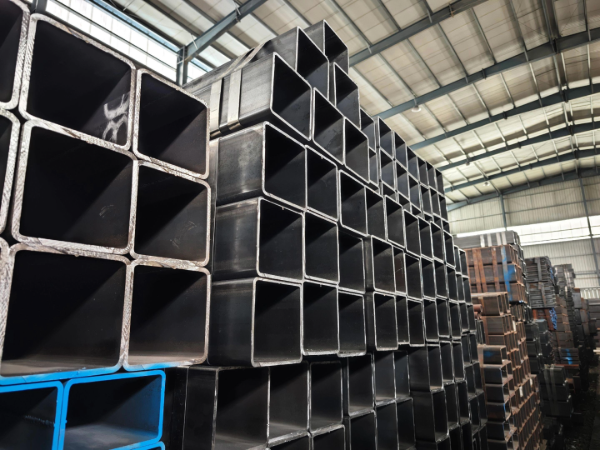
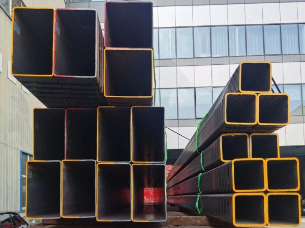
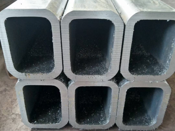
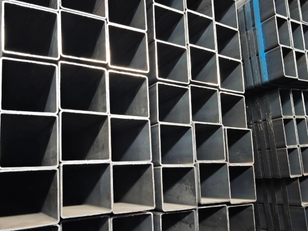
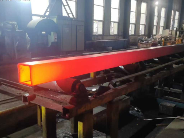
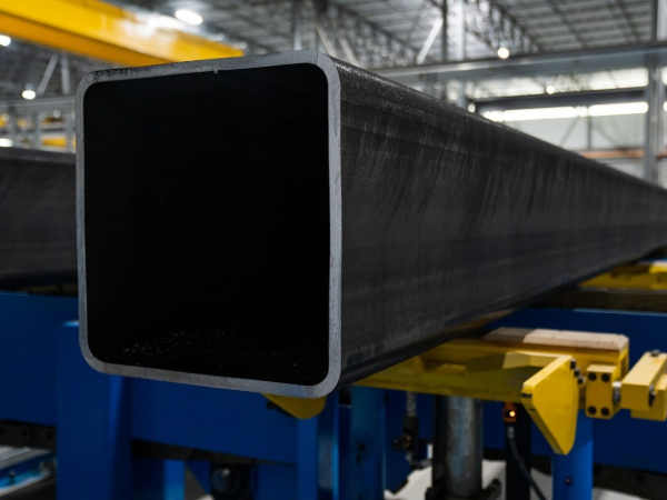
Square Steel Pipe Introduction
|
Application:
|
Widely used in furniture, interior decoration, structure
|
|
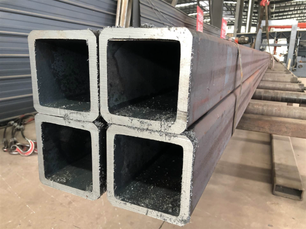
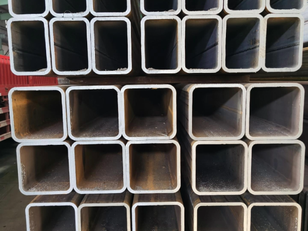
Size:
|
OD: 10*10-1000*1000mm
|
|
Pipe Standard:
|
DIN EN 10210, DIN EN 10219, GB/T 178-2005,ASTM A53, ASTM A500,BS EN 10219,JIS G 3466, ASTM A513, ASTM A36
|
|
S235JR,S355JR,Q235,St37,St37-2,St52,SS400, STK500, Q235B, Q345
|
|
Furface:
|
Black bared, can be galvanized, oiled, painted, powdered.
|
|
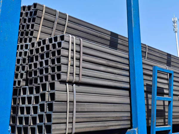
Packing:
|
Waterproof plastic bag, bundle with strip
|
|
Application:
|
Widely used in furniture, interior decoration, structure
|
|
Size:
|
OD: 10*10-1000*1000mm
|
Standard of Square Steel Pipe
ASTM A500 Grade B,
ASTM A513 (1020-1026)
ASTM A36 (A36)
EN 10210: S235, S355, S235JRH, S355J2H, S355NH
EN 10219: S235, S355, S235JRH, S275J0H, S275J2H, S355J0H, S355J2H
|
Size by Inch (diameter)
|
Thickness
|
Sizes by MM (diameter)
|
Thickness
|
|
inch
|
inch
|
mm
|
mm
|
|
1/2" x 1/2"
|
0.065"
|
16mm×16mm
|
0.4mm~1.5mm
|
|
3/4" x 3/4"
|
0.049"
|
18mm×18mm
|
0.4mm~1.5mm
|
|
0.065"
|
20mm×20mm
|
0.4mm~3mm
|
|
0.083"
|
22mm×22mm
|
0.4mm~3mm
|
|
0.120"
|
25mm×25mm
|
0.6mm~3mm
|
|
1" x 1"
|
0.049"
|
30mm×30mm
|
0.6mm~4mm
|
|
0.058"
|
32mm×32mm
|
0.6mm~4mm
|
|
0.065"
|
34mm×34mm
|
1mm~2mm
|
|
0.072"
|
35mm×35mm
|
1mm~4mm
|
|
0.083"
|
38mm×38mm
|
1mm~4mm
|
|
0.095"
|
40mm×40mm
|
1mm~4.5mm
|
|
0.109"
|
44mm×44mm
|
1mm~4.5mm
|
|
0.120"
|
45mm×45mm
|
1mm~5mm
|
|
1 1/8" x 1 1/8"
|
0.035"
|
50mm×50mm
|
1mm~5mm
|
|
0.049"
|
52mm×52mm
|
1mm~5mm
|
|
0.065"
|
60mm×60mm
|
1mm~5mm
|
|
0.109"
|
70mm×70mm
|
2mm~6mm
|
|
0.120"
|
75mm×75mm
|
2mm~6mm
|
|
1 1/4" x 1 1/4"
|
0.049"
|
76mm×76mm
|
2mm~6mm
|
|
0.065"
|
80mm×80mm
|
2mm~8mm
|
|
0.072"
|
85mm×85mm
|
2mm~8mm
|
|
0.083"
|
90mm×90mm
|
2mm~8mm
|
|
0.109"
|
95mm×95mm
|
2mm~8mm
|
|
0.120"
|
100mm×100mm
|
2mm~8mm
|
|
0.135"
|
120mm×120mm
|
4mm~8mm
|
|
0.156"
|
125mm×125mm
|
4mm~8mm
|
|
0.188"
|
130mm×130mm
|
4mm~8mm
|
|
1 1/2" x 1 1/2"
|
0.049"
|
140mm×140mm
|
6mm~10mm
|
|
0.065"
|
150mm×150mm
|
6mm~10mm
|
|
0.072"
|
160mm×160mm
|
6mm~10mm
|
|
0.083"
|
180mm×180mm
|
6mm~12mm
|
|
0.109"
|
200mm×200mm
|
6mm~30mm
|
|
0.120"
|
220mm×220mm
|
6mm~30mm
|
|
0.140"
|
250mm×250mm
|
6mm~30mm
|
|
0.188"
|
270mm×270mm
|
6mm~30mm
|
|
0.250"
|
280mm×280mm
|
6mm~30mm
|
|
1 3/4" x 1 3/4"
|
0.065"
|
300mm×300mm
|
8mm~30mm
|
|
0.083"
|
320mm×320mm
|
8mm~30mm
|
|
0.095"
|
350mm×350mm
|
8mm~30mm
|
|
0.109"
|
380mm×380mm
|
8mm~30mm
|
|
0.120"
|
400mm×400mm
|
8mm~30mm
|
|
0.188"
|
420mm×420mm
|
10mm~30mm
|
|
2" x 2"
|
0.049"
|
450mm×450mm
|
10mm~30mm
|
|
0.065"
|
480mm×480mm
|
10mm~30mm
|
|
0.083"
|
500mm×500mm
|
10mm~30mm
|
|
0.109"
|
550mm×550mm
|
10mm~40mm
|
|
0.120"
|
600mm×600mm
|
10mm~40mm
|
|
0.145"
|
700mm×700mm
|
10mm~40mm
|
|
0.165"
|
800mm×800mm
|
10mm~50mm
|
|
0.188"
|
900mm×900mm
|
10mm~50mm
|
|
0.250"
|
1000mm×1000mm
|
10mm~50mm
|
|
0.312"
|
|
|
|
2 1/4" x 2 1/4"
|
0.188"
|
|
|
|
0.250"
|
|
|
|
2 1/2" x 2 1/2"
|
0.083"
|
|
|
|
0.109"
|
|
|
|
0.120"
|
|
|
|
0.188"
|
|
|
|
0.250"
|
|
|
|
0.312"
|
|
|
Advantages of Square Steel Pipe
Used for a variety of applications, some benefits of square tubing include:
Cost-effective
Strength
Uniformity
Metallurgical Tests
Metallurgical Tests confirm that the chemical requirements of the pipe are as per the material standard.
•Metallurgical Tests are normally known as Micro and Macro pipe inspection & testing.
•Micro Analysis or Chemical Analysis of
1. Raw material
2. Product
3. Weld ensures that all the alloying elements are within the range as specified in the material standard.
•Macro Analysis for Weld will check the proper fusion of weld material with pipe material.
Some special pipe inspection tests are also carried out on the material when it is going to be used in aggressive environments. These tests will ensure that pipe material is able to withstand in such aggressive environments also. Some of the tests are
•Grain size (AS & SS)
•IGC- Intergranular Corrosion Test(SS)
•Ferrite (SS)
•HIC- Hydrogen-induced Cracking
•SSC- Sulfide Stress Corrosion Cracking
These tests are performed when it is asked by the purchaser in his specification.
Destructive Test
The mechanical / Destructive test of pipe inspection confirms the mechanical requirements of pipe are as per the material standard.
In Destructive Testing- a sample from the pipe is cut to perform tests
•The tensile test is done to check the yield and ultimate tensile of the pipe. If required by the purchaser or by standard high or low-temperature tensile tests are also performed.
•Bend test / Guided bend test is used to check the integrity of weld joint
•The flattening test examines the ability of plastic deformation in a pipe
•Impact test / Charpy V-Notch Test, check the ability of a material to withstand low-temperature conditions
•A creep test is done to check the long-term effect of temperature under constant load.